Re-Engineering the DualSense
Part 1: Origins, Motivation, and Early Exploration
I first got into embedded systems before university many years ago, experimenting with microcontrollers and small hardware projects. It never developed into anything serious at the time because I didn’t have any compelling problems to pursue, so the interest faded into the background. The following decade life happened and I also slowly shifted from being a dedicated PC gamer (I put too many hours into Counter-Strike) to being more of a casual player preferring to game from the couch. I never liked using controllers for FPS games, so naturally I didn’t play them as much anymore.
Then, a couple of years ago I found out about using a controller’s gyro for aiming and decided to give it a try. After spending enough hours to become comfortable I found myself having even more fun than the traditional mouse/keyboard setup, and it also meant I could still game casually from my couch. Back then it was mainly a PC-only thing as almost no games had native support for it so one had to resort to mapping the gyro to mouse input using external programs. As of late its popularity has been growing and it has started showing up more and more often as a native feature in games, and players are constantly breaking boundaries in how competitive a controller can be without aim assist in FPS games.
I won’t be covering more about using gyro for gaming in these posts, but you can find more information regarding gyro gaming here.
However, something which has been lagging behind as gyros have been gaining popularity are the controllers themselves. The Playstation 5’s DualSense controller is one of the go-to controllers for it because it has a decent
Wanting to learn more about this, I came up with the idea of “Wouldn’t it be possible to mod a DualSense controller to add these things to it?”, and that’s what this series of posts will be about!
Idea
So you might be thinking “How would this work? We don’t have access to the DualSense’s firmware, and the IMU is a very small component that’s not easy to replace, and even if we could, other IMUs aren’t likely to be drop in replacements? Also, did you forget, last time you tried soldering you ended up bricking your Playstation 3?” (yes, this did happen, RIP!)
The idea I have is that if we can make the Sony microcontroller on the DualSense PCB speak to a microcontroller under our control instead of the original IMU, then we can do things such as disabling the gyro whenever we press or touch a button, and we can use sensor data from two better‑specced IMUs similar to how the Alpakka controller uses dual IMUs.
My goal is to design a circuit that has two high‑specced IMUs and a microcontroller with open‑sourced firmware. This microcontroller will act as a facade between Sony’s microcontroller and the dual IMUs and will perform functions similar to what the Alpakka controller does while speaking the protocol that the DualSense expects. I will later want to design a flex PCB that can be installed on the controller’s PCB with as little soldering as possible (or maybe even no soldering). I do not know too much about electronics or PCB design, but you can get quite far quite fast today with a willingness to learn and an LLM such as ChatGPT to help.
At this point I still didn’t know the details of how the controller talked to the IMU, so the next step was to investigate the PCB more closely. To do this, I started looking for pictures and scans of the various DualSense revisions’ PCBs online. Luckily, I found two things which made the idea seem much more plausible.
Finding the datasheet of the IMU
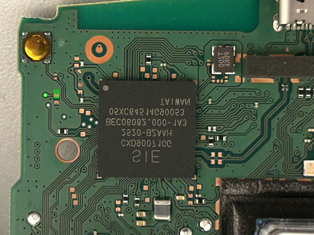
To start off I was able to find a clear picture from a post on Reddit of the 3rd revision (BDM-030), in which I (together with ChatGPT) was able to identify the IMU in the top right corner of the second picture. The IMU has the text I467P on it, and by searching for this it was easy to find that it’s the TDK InvenSense ICM-42607-P whose datasheet is readily available online.
Finding out the pins I care about have test pads
A post on AcidMods has a picture of the 4th revision’s PCB (BDM-040) where an
By cross-referencing the 4th revision’s pins, traces and test pads to the TDK InvenSense ICM-42607-P pinout from its datasheet, it looks like the test pads are coming from the following 4 pins:
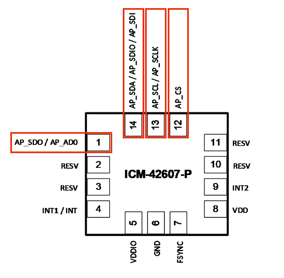
By reading more from the datasheet, we can see that it supports the I²C, I3C and SPI protocols. Looking at the various pinout configurations, we can see that to use the I²C protocol you’re supposed to connect
Committing to the idea
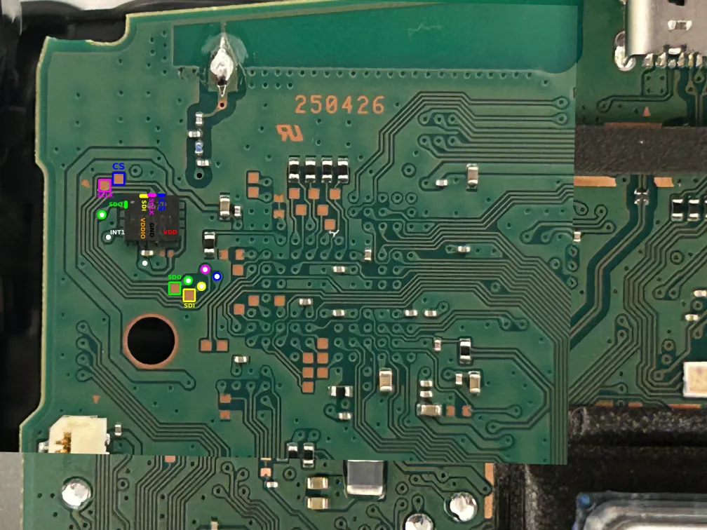
The more I investigated, the more plausible the idea seemed. Since I hope for the final mod to be usable for others, it’s better if it’s made for a revision which you’re still able to find in stores, so I ended up ordering a new controller and opening it up to find that it was the 5th revision - BDM-050. The test pads were still there, and it clearly said I467P on the IMU - great! Assuming it does use SPI, here are some markings for what the pins and test pads are.
Sadly at this point I found posts online saying that a 6th revision had recently appeared. I couldn’t find pictures of it online, but I’m hoping that it doesn’t have major changes in this area.
Shopping List
Another issue I had was that my hardware lab is pretty much non-existant because I threw everything away many years ago (it was very cheap stuff I bought when I was a student). This meant I also needed to buy a lot of things other than a DualSense controller, and while it took me many orders to buy it all, I have summarized the most important things below:
- Raspberry Pi Pico 2
- I have decided to use the RP2350 microcontroller, so the Pico 2 is my choice of dev board.
- 2x Sparkfun LSM6DSO breakout boards
- These use the STMicroelectronics LSM6DSO IMU, which happens to be the same one used in the Alpakka controller.
- Breadboard and jumper cables
- Raspberry Pi Debug Probe
- For programming and seeing debug output from the Raspberry Pi Pico 2
- Raspberry Pi Pico
- Solely for acting as the SPI master during development before I dare connecting my hardware to the DualSense’s.
- A multimeter
- A Saleae Logic 8 Logic Analyzer
- A splurge, but I wanted good support for macOS and if the protocol would be >5MHz I likely wouldn’t get away with a cheap 10€ clone. Worth mentioning that I did make use of their 50% enthusiast discount.
- Soldering and hot air station
- Hot-air station might be overkill, but I thought I might end up needing it at some point and it was only 60€
- Plenty of soldering iron tips in various sizes, mainly very small ones
- Flux
- Lead-free 0.35mm Sn/Cu/Ag solder
- A silicon mat to not ruin my desk
- Desoldering braid
- A small knife
- Anti-static wristband
- Wire of size AWG30 (0.254mm diameter)
- Enamelled copper wire of size AWG38 (0.1mm, almost like thick hair!)
- Kapton tape
- Tweezers
- …another malfunctioning and cheap 2nd hand DualSense controller to practice soldering, scraping vias, and cutting traces on.
Next Up!
In the next post I will be soldering wires to test pads/vias and use the logic analyzer to figure out how the Sony microcontroller communicates with its IMU. After that we can hopefully make up a plan on how to execute on the rest!